A thermistor is a thermally sensitive resistor that exhibits a precise and predictable change in resistance proportional to small changes in body temperature. How much its resistance will change is dependent upon its unique composition. Thermistors are part of a larger group of passive components. And unlike their active component counterparts, passive devices are incapable of providing power gain, or amplification to a circuit.
Thermistor History
Michael Faraday; an English scientist, first discovered the concept of thermistors in 1833 while reporting on the semiconductor behavior of silver sulfide. Through his research, he noticed that the silver sulfides resistance decreased as the temperature increased. This discovery would later lead to the commercial production of thermistors in the 1930’s when Samuel Ruben invented the first commercial thermistor. Since then, technology has improved; paving the road to improved manufacturing processes; along with the availability of higher quality material.
Thermistor Types
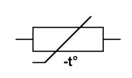
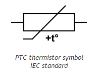
There are two types of thermistors. NTC or Negative Temperature Coefficient thermistors, and PTC or Positive Temperature Coefficient thermistors. The difference is that NTC thermistors exhibit a DECREASE in resistance as body temperature increases, while PTC thermistors exhibit an INCREASE in resistance as body temperature increases.

Applications for NTC and PTC Thermistors include:
- Temperature Compensation
- Temperature Measurement
- Temperature Control
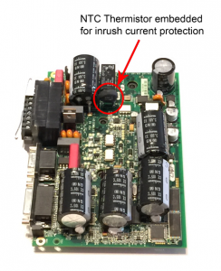
- Inrush Current Limiting
Benefits of NTC and PTC Thermistors
NTC Thermistors are rugged, reliable, and stable, and they are equipped to handle extreme environmental conditions and noise immunity more so than other types of temperature sensors.
- Compact size: Packaging options allow them to operate in small or tight spaces; thereby taking up less real estate on printed circuit boards.
- Fast response time: The small dimensions allow for a quick response to change in temperature, which is important when immediate feedback is required.
- Cost efficient: Not only are thermistors less expensive than other types of temperature sensors; if the purchased thermistor has the correct RT curve, no other calibration is necessary during installation or over its operational life.
- Point match: The ability to obtain a specific resistance at a particular temperature.
- Curve match: Interchangeable thermistors with the accuracy of +0.1˚C to + 0.2˚C.
General Selection Considerations
Whether installing a new system or just replacing a device in an existing system, you should consider these key points before you make your selection to ensure the desired outcome.
- Base Resistance: If you’re installing a new application, be sure to select the right base resistance based on your application requirements. If you are replacing a thermistor, be sure to match the current base resistance.
- Resistance vs. Temperature Curve: If you are installing a new application, determine the correct resistance vs. temperature curve relationship. If you are replacing a device, be sure to match the information from the existing thermistor.
- Thermistor Packaging: Make sure the selected packaging accommodates your application requirements.
For more help with the selection process, visit our page Selecting NTC Thermistors
NTC Thermistors
 NTC Thermistors are non-linear, and as their name suggests, their resistance decreases as temperature increases. A phenomenon called self-heating may affect the resistance of an NTC thermistor. When current flows through the NTC thermistor, it absorbs the heat causing its own temperature to rise.
Applications
- Temperature Measurement
- Temperature compensation
- Temperature Control
Visit our page on Thermistor Applications to get more information on everything from calculating the temperature coefficient of a thermistor to Temperature Measurement with a Wheatstone Bridge.
Benefits
- Fast Response Time to (±1%).
- Accuracy: NTC thermistors have an accuracy range of 0.05 to 0.20 ˚C with long-term stability. Other temperature sensors can drift over time.
- Packaging: NTC thermistors are customizable to meet different application requirements.
- Noise Immunity: NTC thermistors offer excellent immunity to electrical noise and lead resistance more so than other types of temperature sensors.
- Cost efficient: Because of their small size and ease of production, NTC and PTC thermistors prove to be very economical choices.
NTC Manufacturing Process
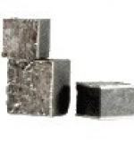
We manufacture NTC thermistors using a mixture of metal oxides such as manganese, nickel, or copper; along with binding agents and stabilizers. The material is pressed into wafer forms and sintered at extreme temperatures; making the wafers ready to either dice into smaller chip style thermistors, or left in the form of a disc thermistor.
Configurations
NTC thermistors are available in different configurations as listed below:

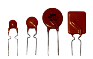
- Disc and Chip: They come configured with or without coating with tinned copper leads with quick response to (±1%). There is also a broad span of resistance values to suit every situation
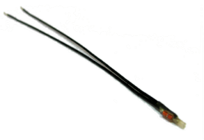
- Epoxy: Epoxy dip coated and soldered between jacketed Teflon/PVC wires. Their small dimensions allow for easy installation, and they can be point or curve matched
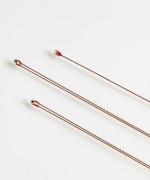
- Glass-Encapsulated: An excellent choice when dealing with extreme environmental conditions. Configurations include radial leaded or axial leaded
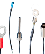
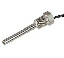
- Probe Assemblies: Available in a variety of housings depending on application requirements
- Surface Mount: Configuration options include Bulk, Tape & Reel, Two-Sided, and Wrap-around with Palladium Silver Terminations. Made with Nickel Barrier, these thermistors work great in precision circuits
NTC Thermistor Glossary
- Dissipation constant (D.C. or delta d): The dissipation constant is the ratio normally expressed in milliwatts per degree C (mw/°C), at a specified ambient temperature, of a change in power dissipation in a thermistor to the resultant body temperature change
- Material constant (Beta β): The material constant of an NTC thermistor is a measure of its resistance at one temperature compared to its resistance at a different temperature. Its value may be calculated by the formula shown below and is expressed in degrees’ kelvin (°k). β = ln (R @ T2/R @ T1) / (T2- 1 – T 1- 1)
- Maximum power rating: The maximum power rating of a thermistor is the maximum power, expressed in watts or milliwatts (W or mW), which a thermistor will dissipate for an extended period of time with acceptable stability of its characteristics
- Steinhart-Hart: This is an empirical expression that has been determined to be the best mathematical expression to determine the resistance-temperature relationship of NTC thermistors and NTC probe assemblies
- Temperature Coefficient of Resistance (Alpha, α): The ratio at a specified temperature, T, of the rate of change of zero-power resistance with temperature to the zero-power resistance of the thermistor. The temperature coefficient; commonly expressed in percent per degree C (%/˚C)
- Temperature tolerance: Temperature tolerance equates to how much variation in ˚C you can expect from a thermistor at a particular temperature
- Thermal Time Constant (T.C. or tau, t): The time it takes for a thermistor to change 63.2% of the total difference between its initial and final body temperature when subjected to a step function change in temperature under zero power conditions. It is normally expressed in seconds
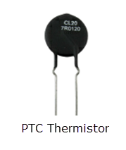
PTC Thermistors
Positive Temperature Coefficient thermistors (PTC) offer a passive approach to limiting inrush current. By implementing a PTC thermistor, you’ll likely see a reduction in operating costs with higher reliability; without compromising protection. PTC thermistors experience a change in resistance if there is a change in the ambient temperature or the device self-heats because it absorbs incoming current. And, since limiting inrush current relies on the specified resistance of a PTC thermistor, making the right selection plays a crucial role in system protection.
PTC Thermistor Types
- Ceramic Switching PTC Thermistors
- Silistor Silicon PTC Thermistors
- Polymer PPTC Thermistors
PTC Thermistor Manufacturing Process
The PTC manufacturing process demands careful control of both the material and particle size as to produce quality devices which contain the proper switching characteristics and voltage ratings.
General PTC Thermistor Applications
- Time Delay
- Degaussing
- Motor Starting
- Overcurrent Protection
If you would like to learn more about PTC thermistors and how they differ from NTC thermistors, visit Wikipedia
Ceramic Switching PTC Thermistors 
This type of thermistor exhibits a highly non-linear resistance-temperature curve. And, because PTC Thermistors possess positive temperature coefficient resistance, they show a trace amount of negative temperature coefficient until they reach a critical temperature point known as a “curie” or transition state. When this happens, the device will begin to exhibit a positive temperature coefficient and a significant increase in resistance.
Manufacturing Material
Ceramic Switching PTC thermistors are manufactured using a polycrystalline ceramic material that contains barium titanate, which has been doped with rare earth materials to give it positive temperature coefficient resistance.
Applications
- Over-Temperature Protection
- Over-Current Protection
- Temperature Compensation
- Time Delay
Benefits of PTC Thermistors for Inrush Current Limiting
To demonstrate the versatility of PTC thermistors, below are some examples where their use as an Inrush Current Limiter is the optimal choice.
- Ambient temperature is greater than 65 °C.
- Ambient temperature is less than zero °C.
- Reset time needs to be near zero °C.
- Short circuit concerns.
Visit PTC Thermistors for Inrush Current Limiting to see how a PTC thermistor compares to an NTC thermistor, and get more information on special circumstances where a PTC thermistor is clearly the best choice for limiting inrush current.
Configurations
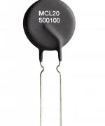
- Radial Leaded
- Surface Mount
PTC Thermistor Glossary
- Dissipation constant (D.C. or delta d): The dissipation constant is the ratio, normally expressed in milliwatts per degree C (mw/°C), at a specified ambient temperature, of a change in power dissipation in a thermistor to the resultant body temperature change.
- Heat capacity (Hc): The heat capacity of a thermistor is the amount of heat required to increase the body temperature of it by one degree centigrade (1°C). Heat capacity is a common rating of standard PTC thermistors and is expressed in watt-second per cubic inch per degree C (watt-sec / i n3/°C). The heat capacity per unit volume relationship of standard PTC thermistors is approximately 50 watt-sec / i n3/ ° C.
- Maximum steady state current (Imax): The maximum steady state current is the rating of maximum current, normally expressed in amperes (A), allowable to be conducted by an inrush limiting NTC thermistor for an extended period of time.
- Operating Temperature: Operating temperature is a range of temperatures that a thermistor can operate in without failure.
Switch Current: Minimum amount of current, normally expressed in amperes (A), that when conducted by a standard PTC thermistor, is required to cause it to switch to its high resistance state. - Switch Temperature: The temperature of a standard PTC thermistor at which its resistance begins to increase at a rapid rate.
- Switching Time: The amount of time required for the PTC to switch into its high resistance state.
- Switch Transition Temperature: Two-times a PTC’s zero power resistance at 25 ˚C.
Silicon PTC Thermistors
Silicon “Silistor” PTC thermistors are linear devices which display significant positive temperature coefficient resistance. However, should the temperature exceed 150 °C, they would most likely exhibit negative temperature coefficient.
Applications
- Temperature Compensation
- Temperature Sensing
Benefits
What’s so special about silicon thermistors? For one thing, silicon is inherently a stable material, so if you’re in need of a thermistor that offers both stability and longer operational life, silicon thermistors would be a good choice.
Other benefits include:
- High-Temperature Coefficient
- Multiple Configurations
- High Reliability
Manufacturing Material
The materials used to manufacture Silicon Silistor thermistors are a composite of polymer materials like semiconducting monocrystalline silicon as well as other conductive particles.
Configurations
- SMD Chip
- Epoxy
- Glass-Encapsulated
- Probe Assemblies
Polymeric PPTC Thermistors
The Polymeric thermistor (PPTC) is a positive temperature coefficient thermistor also known as a “Resettable Fuse,” and they display a nonlinear PTC effect. Because they are thermally activated devices, any fluctuation in ambient temperature will have an impact on the performance of the thermistor. Under normal operating conditions, the Polymer PTC displays minimal resistance compared to rest of the circuit, and it has little to no impact or influence on the circuit performance in whole.
However, if the circuit system goes into a fault state, the PPTC responds by going into a high resistive or “tripping” state. Once you have eliminated the fault conditions, the PPTC resets itself, and the circuit returns to its normal operating conditions. Visit Wikipedia for more information on Resettable Fuses and how they work.
Applications
- Process Control and Medical Equipment Protection
- Consumer electronics
- Automotive
- Telcom
Manufacturing Material
Non-conductive crystalline organic materials, mixed with carbon black particles are used to construct polymer thermistors, which is what causes them to become conductive.
Benefits
You should consider PPTC thermistors if you experience frequent overcurrent conditions, and or the application requires constant uptime. You can’t deny that component cost is not the only concern. The demand for smaller technologies like wearable devices is not going away, and protecting the circuitry is critical. The costs of warranty repairs can quickly outweigh the cost of the sensors that protect them. If you need to determine the reliability of a thermistor for your application, visit our page Reliability of a Thermistor to view the formula for calculating a PPTC thermistors reliability.
Other benefits include:
- Resettable
- Compact Size
- Minimal Power Loss.
- Low Resistance
- Configurations
- Radial Leaded
- Surface Mount
Visit Wikipedia to learn more about polymeric PPTC thermistors.
Polymeric PPTC Thermistor Glossary
- Hold current: Hold current is the maximum steady state current that can be passed through the PPTC resettable fuse at 23 ˚C without causing it to trip.
- Maximum Current: The maximum current is the maximum fault current that can flow through a PPTC.
- Maximum Initial Resistance: This is the maximum resistance of the PPTC in its initial state at 23 ˚C.
- Maximum Voltage: Maximum voltage is the maximum amount of voltage a PPTC can be exposed to.
- Minimum Initial Resistance: This is the minimum resistance of the PPTC in its initial state at 23 ˚C.
- Post Trip R1: This is the maximum resistance of a PPTC one hour after it has been tripped.
- Power Dissipation: Power dissipation is the amount of dissipated power when the PPTC is in a tripped state.
- Time to Trip: This is the time it takes for a PPTC to switch to a tripped state once a specific current is applied.
- Trip Current: Trip current is the minimum current flowing through the PPTC that will cause it to trip at 23 ˚C.
![]()
Thermistor Resources
Thermistor Math
- NTC Thermistor – Calculating the Temperature Coefficient of a Thermistor This article provides you with an equation you can use to calculate a thermistor’s temperature coefficient. The temperature coefficient is the change that occurs in the resistance with a change in temperature. A useful and frequent customer example is provided.
- The Secret to Successful Beta Calculations: This article explains beta value and how to calculate thermistor beta with examples.
- The Steinhart and Hart equation is an empirical expression that has been determined to be the best mathematical expression to determine the resistance-temperature relationship of NTC thermistors and NTC probe assemblies.
- Thermistor Terminology: When learning about thermistors, here are some other terms you’re likely to encounter.
![]()
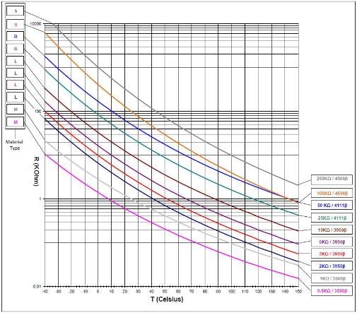
Probe Assembly and NTC RT Curves
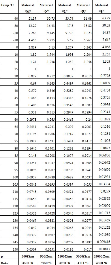
Temperature Coefficient Chart
We’re here to help
Here at Ametherm, our mission is to ensure that you have all the necessary tools and knowledge to get the job done right the first time. That’s why our engineering team is always available to assist you. Connect with us at 800-808-2434 or 775-884-2434 where you’ll get live technical support. You can also go online to ask us a question anytime. Your success is our success!
Evaluate our products
We know that getting the right thermistor for the job is important, so we encourage you to test our products before you commit to purchasing something that turns out not to be the right solution. Contact us to order your free sample and we’ll ship it within the USA and Canada at no charge to you. Reach us at 800-808-2434 or 775-884-2434 or click here to get started.
Our products are available for immediate delivery through our stocking distributors. Please feel free to visit their sites for more product information.

![]()


