A Comprehensive Overview of Thermistor Circuit: Principle, Types, and Diagram
Physics will always be inadequate if we don’t talk about thermistor circuits. Well, these are remarkable devices and are the innovation of Michael Faraday; he was the one who bought the concept of light. He was the first inventor of the thermistor circuits in 1833. The thermistor is a hybrid of the resistor and thermal. The most common thermistor is the RTD; it is highly sensitive to temperature. There are many great features and working principles of thermistors. In this article, we will talk about the science behind thermistors and discuss all about it.
Basic Principles Of Thermistor Circuits
The thermistor principle is based on a manner to allow the devices to function in a manner that does not cause any disturbance. Read the following for more information:
- The thermistor circuit is a metallic device that operates a resistor with a working method similar to the semiconductor with a negative resistance.
- The thermistor’s resistance is directly based on the temperature. With high temperatures, there is more resistance.
What Are The Parts Of Thermistor Circuit?
Thermistor circuits cannot survive without their essential components, such as:
- The specific metallic tube containing sensors within the thermistors.
- The wiring network comprises a lead that extends out from the thermistors.
- The fine insulative layer divides the thermistor from the metal tube.
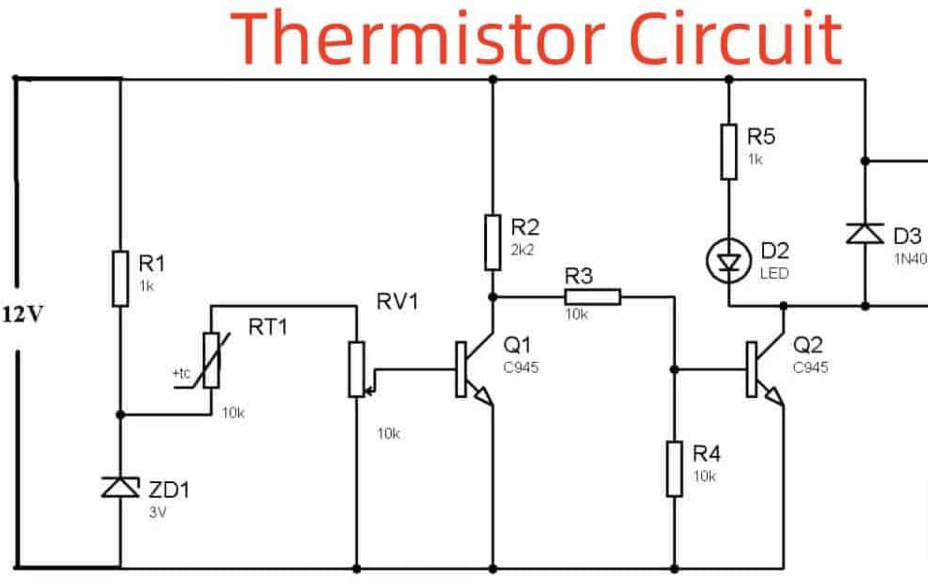
When you look at the thermistor diagram, you can understand their connections and how all these parts play a major role in Thermistor circuits.
Types Of Thermistor Circuits
Following are some of the common thermistors types:
Negative Temperature Co-efficient Thermistor Circuit
- In this type of thermistor, the temperature and resistance are inverse.
- You can trust the thermistor when you want to record the temperature changes and the amount of currents.
- These thermistor circuits are very sensitive to a slight change in temperature. Hence, they are reliable for censoring the temperature changes in an electrical device.
- It maintains the resistance low and allows more current to pass through the system until it reaches the optimum level that is useful for devices such as fire censoring equipment, ACs, and baking ovens.
Positive Temperature Coefficient Thermistor Circuit
- This type of thermistor circuit is directly proportional to the temperature. The resistance will increase with the temperature.
- You align the PTC thermistor circuits in series that help to cope with the electrical fuses.
- These are the best for guarding the system against the overcurrents leading to glitches and electrical fuses.
- There are type primary types of PTC thermistors; the following takes a good look at them.
o Silistor Temperature Sensor:
It has a silicon structure and follows the linear temperature graph for smooth functioning. The resistance will follow the temperature in case it increases.
These thermistors are available in the market in fewer quantities since their demands are declining.
- Switching Type Circuit
It is another PTC thermistor type that serves as the NTC thermistor.
Some substances tend to undergo sudden changes in nature after crossing the curve point.
There is a particular temperature limit; once exceeded, the nature of the thermistor circuit will change.
The resistance after crossing the curve point will enhance quickly.
The applications of this PTC thermistor are for mid to small-range heaters, thermostats, and electric motors.
Disk and Chip Thermistor Circuit
- This type of thermistor has fine metallic contacts.
- The size of this thermistor is bigger than others.
- They generally have lagging responses to other variants.
- The copper bar is fundamental for maintaining the sensitivity of the thermistor on the accounts.
- Such thermistors also provide remarkable endurance for tackling high current levels.
- Due to its remarkable features of thermistor principle, it can provide top-notched performance than bead thermistors.
Epoxy Thermistor Circuit
- You will need industrial-grade epoxy solder for the wires that are made up of PVC and Teflon.
- The size of the wires is small.
- With its small size, this type of thermistor circuit does not need an extensive process for assembly. You can refer to the thermistor diagram for more details.
- You can change the position and shape of the wires without any hassle.
Bead Thermistor Circuit
- The wiring of this type of thermistor is best for platinum.
- You must also connect them with the ceramic to enhance their performance.
- These thermistor circuits are delicate.
- These are more reliable since they respond quickly and provide more stability. Another good thing about them is that they can handle high temperatures.
- Since they are sensitive and delicate, a protective glass covering is necessary.
Glass Encapsulated Thermistor Circuit
- This type of thermistor circuit shows efficient performance when talking about severe temperatures.
- There are glass layers that encapsulate the thermistor.
- They provide high stability and are reliable for severe environmental changes.
Probe Assemblies
- In this, you will use the thermistor circuits daily in your life. The air conditioners and geysers use probe assembly thermistors.
Surface Mount Thermistor Circuit
- These thermistors have essential applications in the motherboard of PCs and Laptops.
Composition and Structure Of Thermistor Circuits
The thermistor diagram and shapes have no boundaries. Customers use different thermistor types for their specific uses. Industrial producers generally rely on several shapes and sizes based on their projects. The different types have different production materials as well. Nickel, Iron, and cobalt are the recommended materials that are handy for making such thermistors. You will have to grind the metallic oxides and turn them into a powder-like form.
After the process, you will get a compact powder known as centering. This powder allows you to create different shapes of thermistors according to your needs. The thermistor working principle remains the same regardless of their shape and size.
Tools such as probes shape the thermistor circuits into bead or rod-like thermistors. You will also have to determine the temperature range for making the thermistor. Different metals have their ranges, so you must ensure that the thermistor is best for the application.
Benefits Of Thermistor Circuit
There are many benefits of using thermistor circuits. You will be grateful for such an invention after learning the following benefits:
- Incubators used in the lab have thermistors for monitoring the temperature of the samples.
- A thermistor is more cost-effective than other costly temperature regulatory sensors and devices.
- Water cannot affect these thermistors, so they are the best option for moisture and water.
- The properly developed thermistor has sufficient strength.
- Thermistors are easy to shape, making them a more convenient option for consumer electronics.
Working And Testing Of Thermistor Circuits
Two affect the performance of the thermistors: resistance and temperature. The temperature and resistance also affect each and change according to the situation. It is necessary to check the thermistors to ensure their fine performance. There are tools such as multimeters and ohmmeters that help with the testing.
If you are dealing with the PTC thermistor, you will have to check the thermistor circuit diagram to learn how you can join its ends with the multimeter. When you heat the sensor, you will see that the resistor will increase. It indicates that the PTC thermistor is proportional to the resistance in the case of the PTC thermistor. The resistance tends to alleviate for the NTC thermistors because of the inverse relation.
Conclusion
These are all about thermistor circuits and their usefulness in our day-to-day products. By learning about the thermistor circuit diagram, you can ensure that the consumer electronics always work the same without any issues and fix them before they ruin the devices.